Working With OpenSCAD
OpenSCAD Series - Part Two

The 3D modeling tool OpenSCAD was introduced in a previous article. OpenSCAD allows the modeling of complex 3D objects being built up from simple primitive shapes. The modeling is done with a simple programming language. Using this language the modeler can create simple to very complex objects.
We will be covering how to install OpenSCAD on a Windows and Mac OS, how to create our first simple object and finally how to export the complex object as an SLT file. An SLT file can be further processed by a slicer, such as Ultimaker's Cura, for printing on a 3D printer.
How to install OpenSCAD
A the time of this writing the current version of OpenSCAD is 2021.01 which was released on February 6th, 2021. OpenSCAD seems to go through releases about every 18 to 24 months. To install the newest release go to the OpenSCAD webpage:
https://openscad.org/downloads.html
Windows:
- Download the release that best fits your system architecture.
- Windows users can download either a 32 bit version or a 64 bit version as either an exe installer or a zip file.
- If you are using a modern version of windows (10 or newer) select 64 bit exe installer.
- Double-click the installation package. It requires administrator rights to install – grant those rights when requested. (Note: If you do not have administrator rights on your PC – download the zip file version and manually install it.)
- The installer opens with the following dialog window – click the Install button.
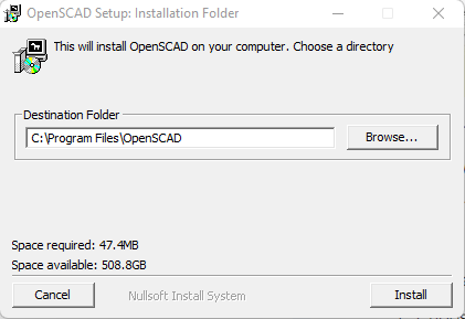
- Desktop and Start Menu shortcuts will be created.
Mac OS:
Only a 64 bit intel version is available for the Mac. As of this writing the Mac OS still supports this architecture in compatibility mode on Apple silicon.
- Click the download for the Mac – it is a dmg package.
- Double-click the dmg package to extract the application.
- Drag the OpenSCAD application to your Applications folder
Linux:
There are multiple packages available for Linux users and it can be installed from the Snap Store and Flathub as well. We will not be covering the Linux install; most Linux users should fine the installation to be very straight forward.
Setting Up the Program
When first opening OpenSCAD you will see a simple launcher / splash screen. From here you can open projects you have recently worked on, open examples or start a new project:
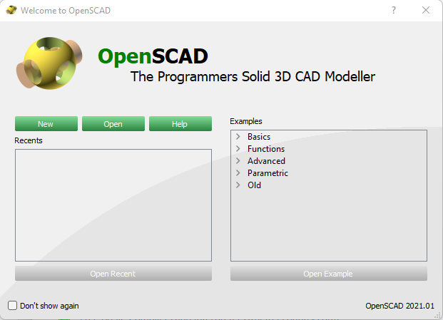
Click the New button to start a new project.
I am using Windows, but everything I do here should work the same way on other supported operating systems also. Before we start creating we need to make some adjustments and explain the environment.
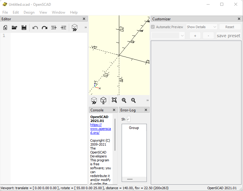
Adjust the views in the program to make it easier to work with.
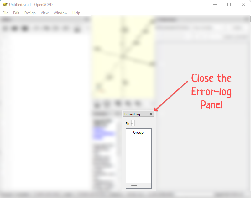
- Close the Error-log panel if it is open
- Close the Customizer panel if it is open
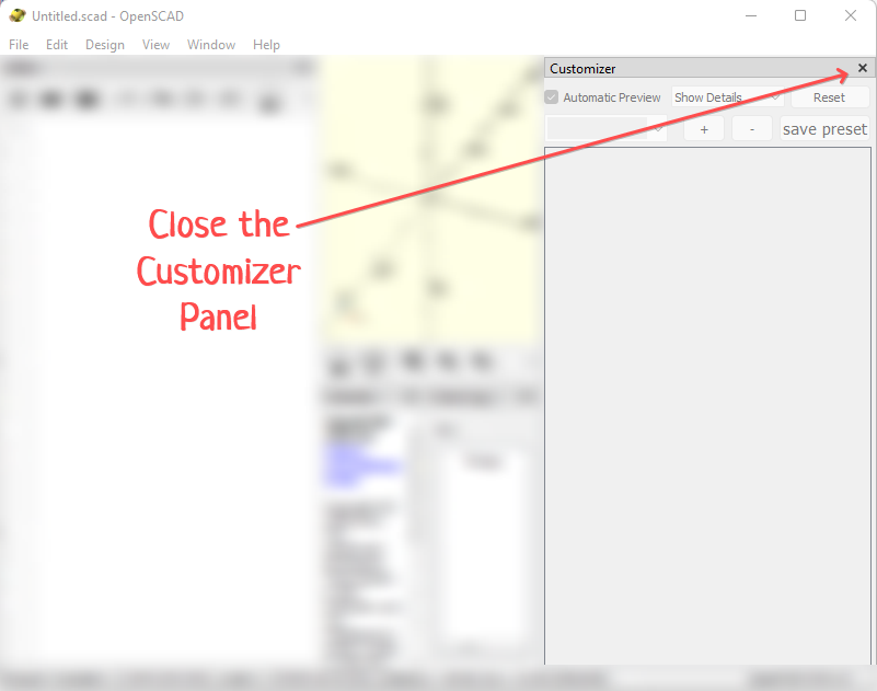
- Drag the panel splitter between the yellow panel and the console - sizing shrinking the console down to just a few lines of text.
- Finally drag the panel splitter between the yellow panel and the Editor – enlarging the yellow panel and shrinking the editor. It should look like this:
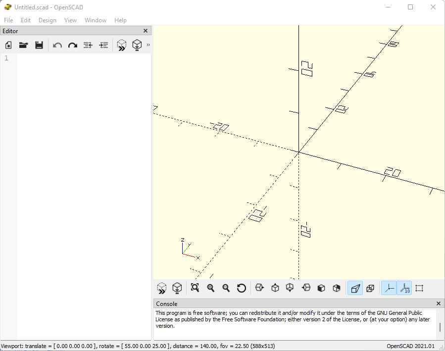
The application window is divided into three parts – called panels - typically (although there can be additional panels open if desired). These panels are:
- Editor – where you will write the code that produces the 3D object.
- Preview – Where you will see the results of running your code.
- Console – Where status messages and error messages will be displayed.
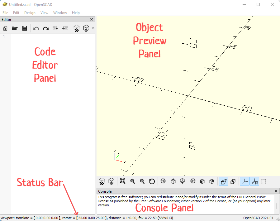
Preview Panel
The view within the preview panel can be rotated, panned and zoomed using the mouse. Move the mouse into the preview panel.
- Left mouse button – holding this button and moving the mouse will cause the view to rotate around the center axis in 360 degrees in all directions.
- Right mouse button - holding this button and moving the mouse will cause the view to be panned left, right, up and down.
- Mouse wheel (or center mouse button) – when the mouse wheel is rolled (or the middle mouse button held down while the mouse is moved) the view will zoom in and out.
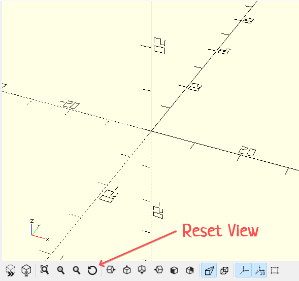
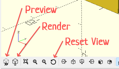
- Reset - Return the view to its original view setting by pressing the Reset View icon in the panel’s button bar at the bottom.
Code Editor
Code will be written in the Editor panel. At the top of the Editor panel is a toolbar that contains several important commands that will be used regularly and several that are nice to have.
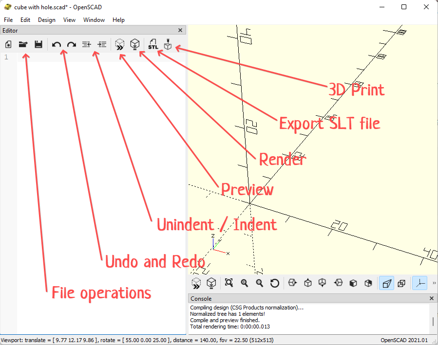
- File Operations – these include New, Open and Save. I recommend saving your work regularly as you design a shape or model. Click the save icon is quick and easy.
- Undo and Redo – these options are self-explanatory. Recover from an oops!
- Indention – The buttons to unindent and indent are very convenient and tend to get used a fair amount.
- Preview – The preview button is the general work horse of the application. It instructs OpenSCAD to run the code and render a quick interpretation of the object you have created. It is fast but sometimes does not look perfect. (The Preview button is both on the Editor and Preview panel toolbars)
- Render – The render button will produce a high quality version of the object you have created. It is very precise and well rendered, but can take a fairly long time depending on the complexity of the object and the speed of your computer. (The Render button is both on the Editor and Preview panel toolbars)
One last important thing to mention. The application has a link to a cheat sheet in the Help menu: Help -> Cheat Sheet. This is an invaluable resource when programming your creation. Open it before you start and reference it as you go.

Creating Your First 3D Object
The object we are going to create will be a cube with a round hole passing through it from top to bottom.
We will begin with a cube object. The cube operation can be looked up on the cheat sheet.
Here is what it says:
Creates a cube in the first octant. When center is true, the cube is centered on the origin. Argument names are optional if given in the order shown here.
cube(size = [x,y,z], center = true/false);
cube(size =  x ,     center = true/false);
parameters:
size
- single value, cube with all sides this length
- 3 value array [x,y,z], cube with dimensions x, y and z.
center
- false (default), 1st (positive) octant, one corner at (0,0,0)
- true, cube is centered at (0,0,0)
Type the following on line 2 of the Editor (leave line 1 blank):
cube(16, center = false);Note: Make sure each of your lines of code ends in a semi-colon as show above – you will get an error if you forget the semi-colon. Also, case matters. Make sure your operations are spelled with all lower case letters.
Now click the preview button in the one of the toolbars:

You should see the following:
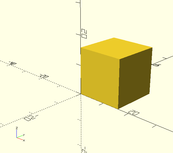
If you get an error verify that all the characters are lower case and that the trailing semi-colon is present.
Next will need a cylinder.
The cylinder has some pretty complex options. With we can make a cone or a shape like a can or many transitional shapes between these. We will be making a simple can with equal sized top and bottom round surfaces. For this we will only need height and radius. The simplified statement looks like this:
cylinder(h=height, r=radius, center = true/false)Type the following into line 4 of the Editor (leave line 3 blank)
cylinder(h=18, r=5);Click the preview button in the one of the toolbars:
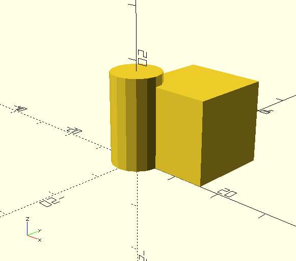
(If you got an error – double check you code. Also make sure you remembered the semi-colon and all operations are spelled with lower case letters.)
Now take a look at the cheat sheet. Find the section called Transformations. These are all statements that allow the modification of the object chained to the operation in some way. These allow moving (translate), rotating and scaling of objects as well as many other operations. Of these you will use translate very frequently.
As indicated - translate moves the object that is chained to the operation. When we say an object is chained to an operation it means that the multiple operations have been linked as if in a chain. Each operation in the chain will modify the final object (or objects) they are chained to.
We are going to use translate to move the cylinder we created into the center of the square.
This is what the cheat sheet says about translate:
Translates (moves) its child elements along the specified vector. The argument name is optional.
Example:
translate(v = [x, y, z]) { ... }The child elements are grouped into a set inside curly brackets. If there is only one child element the curly brackets are optional. The “v=” part of the statement is optional. A value must be provided for each of the three vectors x, y and z and they must be contained in square brackets.
In our case we will move the cylinder 8 units in the X direction, 8 units in the Y direction and one negative unit in the z direction.
There is a handy cheat in the Preview panel showing you the direction of each of these vectors. It looks like this:

Add the following line of code on line 3 (which we previously left blank):
translate([8,8,-1])Notice that this line did NOT require a semi-colon. That is because it modifies the line that follows it (which is chained to it), and acts as part of that statement, which provides the required terminator. In essence we are saying:
translate([8,8,-1]) cylinder(h=18, r=5);Click the preview button in the one of the toolbars:
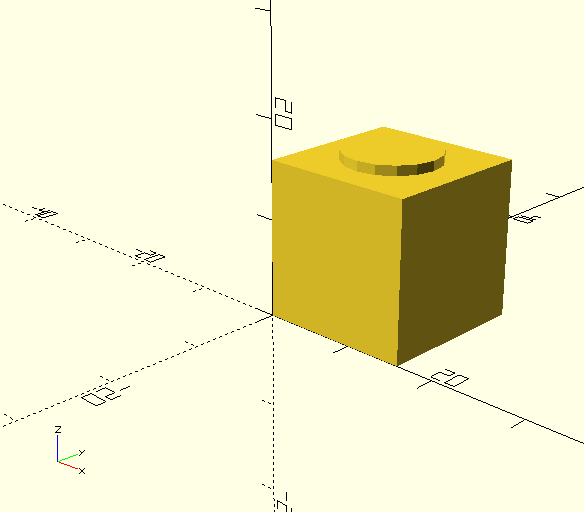
(If you got an error – double check you code.)
Removing The Center
To finish this example we will subtract the cylinder from the cube. Subtracting one object from another creates a void or opening in the object from which it is subtracted. This type of operation is part of Boolean Operations. The statement we will use is difference.
The cheat sheet describes difference this way:
Subtracts the 2nd (and all further) child nodes from the first one (logical and not). The statement is constructed like this:
Difference() {
  Operation 1;
  Operation 2;
}
Difference requires parentheses and the statements that are being operated on must be contained in curly brackets.
Add the following statement to line 1:
Difference() {One line 5 add a single closing curly bracket: “}”
The finished code should look like this:
difference() {
cube(16, center = false);
translate([8,8,-1])
    cylinder(h=18, r=5);
}
Click the preview button in the one of the toolbars:
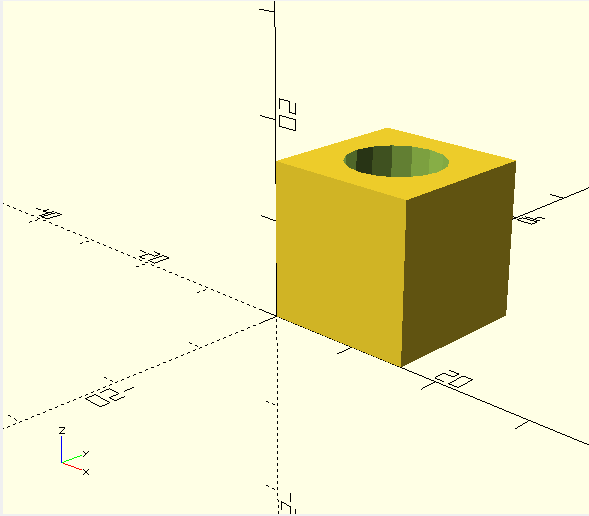
(If you got an error – double check you code.)
You might be wondering if you need to plan your code for future statements, leaving blank lines for them as we did here. Certainly not! In fact we are going to add one more statement to our program that will cause the cylinder to look more rounded. Read about it here.
Place your cursor at the beginning of line 1 and hit ENTER. This will create an empty line and shift your code down one line. Type:
$fn=90;Click the preview button in the one of the toolbars. Looks better. Rotate you view around and have a look at the finished object. Now click the Reset View button.
Finally click the Render button. All of these buttons are on toolbar at the bottom of the Preview panel:
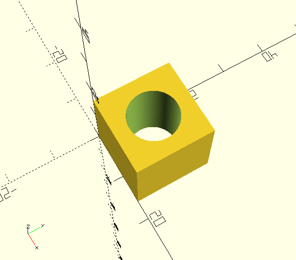
Here is the final object rendered. I have rotated it around a little with the right mouse button:
Go ahead and save your first project.
(Note – save your drawing in your personal home directory or your personal documents directory – depending on your operating system. Do not save them into the installation directory. Create a new folder for them if you must.)
Exporting Your Object as an SLT
One final thing to accomplish this time. That is to export this object as an SLT file. If you are familiar with 3D printing then you will recognize that an SLT file is the source file from which you will generate a sliced object for printing.
OpenSCAD makes generating an SLT file fairly simple. There is one requirement before you can export your object. You must render it in high quality. If you forget this step OpenSCAD will warn you:

Note: Be aware that if you proceed to export an object that you have not rendered it will export that latest rendering which may not include your most recent changes.
We just did this for our object, so it is ready for export. If you have made any changes to your code – be sure to render the image before proceeding.
Click the SLT button in the editor toolbar or from the File menu select File -> Export -> Export as SLT. Choose where to save the SLT file.
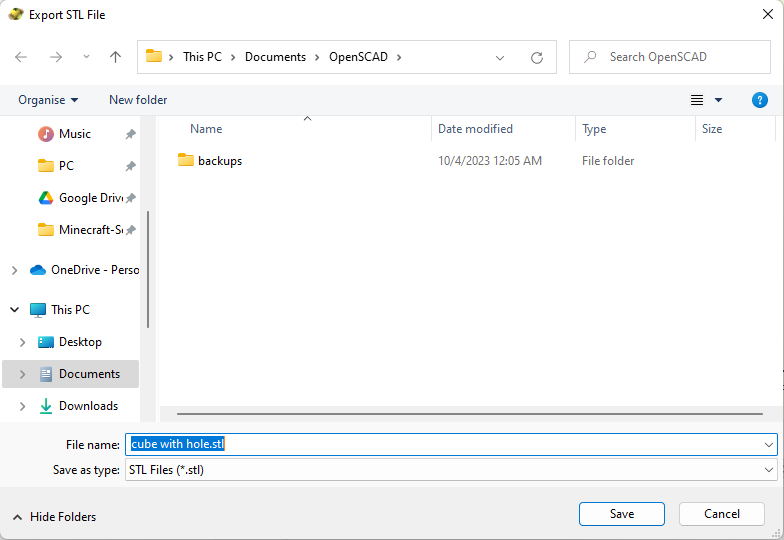
That is it – an SLT file has been generated and it can be easily sliced with a program like Ulitmaker's Cura.
Units in OpenSCAD
One of the things not discussed yet is units of measure. Officially OpenSCAD is unit agnostic, meaning it really does not care what unit of measure you are using. In practical terms knowing the unit you are working in is critical to designing a practical object.
In my experience working with OpenSCAD and the Cura slicer you can consider the unit of measure the base unit of the device you are printing with. For nearly all printers that is 1 mm.
That means the object we designed is 16 mm square. For those of using the imperial measuring system that is about 2/3rds of an inch. Not very big.
We could make it bigger using the scale operation. Here is what the cheat sheet tells us about scale:
scale Scales its child elements using the specified vector. The argument name is optional.
Usage Example:
scale(v = [x, y, z]) { ... }
The variables x, y and z are multipliers. If we want half size we multiply by .5. If we want double we multiply by 2. In this example the cube is being scaled differently in each of the three directions x, y and z. Specifically it is half size in the x direction, full size in the y direction and double size in the z direction.
cube(10);
translate([15,0,0]) scale([0.5,1,2]) cube(10);
Lets make the object three we created times larger. Insert a new line after line 1. Add this statement into the newly created line 2:
scale([3,3,3])This line does NOT need a semi-colon at the end, as it is chained to the operation that follows it – in this case the difference operation.
Preview the object with the current changes. You may need to zoom out a little (with the mouse wheel) to see the newly rendered object. It is now 4.8 cm (about 2 inches) square.
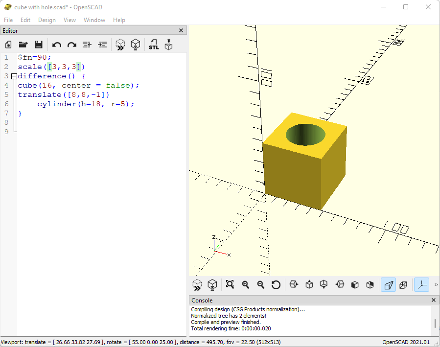
This is the finished code for this project:
$fn=90;
scale([3,3,3])
difference() {
cube(16, center = false);
translate([8,8,-1])
    cylinder(h=18, r=5);
}
Don’t forget to save your work.
Looking Ahead
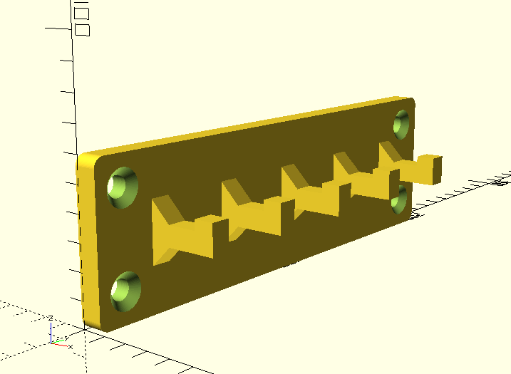
Next time we will be creating a much more complex object. Specifically, we will build a wall mountable key hook rack. We will be using many more operations, learning about Modules, Extruding and using the Minkowski operation to apply a rounded edge to a rectangular shape. Here is what we will be creating:
See you next time!


